582
Fitting a Moss headlamp relays
kit
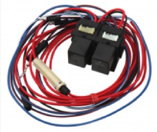
Twin relays kit from Moss Europe
Visit the Moss
Europe website
Fitting instructions from Moss Europe
See a copy of the three page instructions. More
See a copy of the full article. V8NOTE582
Posted: 200319
|
|
Fitting
a Moss headlamp relays kit
With MGBs and derivatives like the MGBGTV8 now approaching the
50 year milestone, modifications that help preserve electrical
components such as switches are well worth considering as they
are not difficult to install or costly. This useful upgrade
uses relays to take the load and potential damage off the ageing
switches. Here we have a step by step guide from Andy Goves
describing how he had a ready wired twin relays kit (see below)
supplied by Moss Europe fitted to his 1973 MGBGTV8.
Installation of the pre-wired twin relays kit
Chris Smith had provisionally allocated four hours for this
work (knowing my commitment to originality), anticipating the
difficulty would be locating the modern looking relays out of
sight. In fact it only took Chris one hour to complete the whole
installation!
The approach adopted considered these criteria:
> Preserve the original appearance of the engine bay and
electrics.
> Accept the need to lengthen wiring, if necessary, to achieve
this objective.
> Achieve proximity of new relays to existing headlamp wiring
harness.
> Siting of new relays needs to avoid water ingress.
> Relays will operate in a horizontal or vertical position.
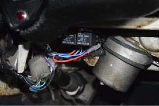
A suitable location was found (see photo alongside) adjacent
to the headlamp wiring harness that allowed both relays to be
fixed horizontally to the metal structure under the dashboard,
near to the windscreen wiper motor, providing a good earth connection.
This is very convenient for the bullet connectors for the headlamps
wiring; in addition the original equipment switch plug could
be unpicked to remove the pins and avoid cutting any wiring.
The Moss Europe unit is extremely well produced and offered
an opportunity to continue to use the bullet connectors thus
maintaining originality. However, I opted for soldered joints
to give a higher degree of reliability, noting that there would
be no stress or movement imposed on this new wiring.
The red main 12v feed (item 30 in the annotated photo on page
1) already contains an online fuse and is routed through the
main wiring loom rubber grommet in the bulkhead into the engine
bay and onto the fuse box, taking care not to damage the grommet
as it can become brittle with age. An adequate length of wire
was provided with the kit, with no extension required.
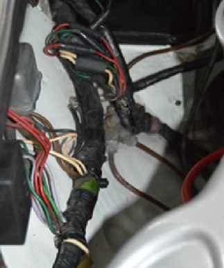
Before doing so, a black insulating sleeve was placed over the
entire red wire and then heat shrunk to fit - the new wire now
looked part of the original wiring loom, being secured below
the existing black insulated wiring loom in the engine bay (see
photo above right). Although done for purely aesthetic purposes,
this sleeve provides additional protection against any abrasion
which might, in extreme cases, result in a short circuit, acknowledging
that the in line 20 amp fuse should provide primary protection
here. |


