535
Fitting
a dual circuit brake servo to an MGBGTV8 conversion
As part of the
conversion of his MGBGT to V8 specification in 2008, Mike Howlett fitted
dual circuit brakes to a 1969 chrome bumper MGBGT using the In-line Master Cylinder
and Servo. Here Mike describes the job.
One of the improvements that I
decided on early in the planning of my MGBGTV8 Conversion was to use the late
model twin circuit brake master cylinder with a direct acting servo. Accordingly
I purchased from Andy Jennings a complete late model pedal box with cylinders,
servo and pedals. This cost me £45 in 2006. I stripped the assembly down,
and cleaned and painted the parts. A new brake master cylinder was bought, but
for the servo I simply dismantled it, painted the case and reassembled it using
a servo repair kit. As the inline servo does not have brake fluid in it, the internal
components were in excellent condition. There is an issue with the clutch master
cylinder, but I'll come to that later.
Holding the new pedal box up to
the car showed that the bolt holes are in the same places, so no extra drilling
would be required for them. However, the brake pedal is hung in a slightly different
way and fouls on the rear of the original square aperture. I extended the aperture
rearwards by 30mm to give clearance (see photo).
Bolting the servo to the
pedal box and offering it up showed that there was a small area of conflict with
the servo body and the inner wing. A little dressing with a hammer soon gave sufficient
clearance.
When I was finally ready to fit the pedal box I found that
both pedals together will not go through the aperture from the top. On the bench
I removed the | 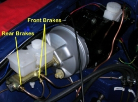
clutch pedal, bolted the servo on the box and connected it to the brake pedal.
I bolted the clutch master cylinder to the back of the box. Then I manoeuvred
the brake pedal through the hole, fiddled the rubber gaskets in place under the
box and bolted it down. This was a bit awkward as some of the bolts are in the
narrow gap between the pedal box and the inner wing. Then I introduced the clutch
pedal from beneath. You can either use an assistant to push it up, or haul it
up on a piece of wire as I did. I bolted the clutch pedal in place and connected
it to its master cylinder.
The brake master cylinder bolts on the front
of the servo and fits under the bonnet line nicely. I found that on my car, the
manual bonnet prop did not get in the way. If you have a telescopic prop, you
might have to move it to the left side of the car as the factory did.
The
cylinder has three outlets, two in the first stage and one in the second stage.
I connected the two front brakes to the twinned
outlets, and the rear brakes to
the second stage outlet. This way if one circuit fails I should still have either
front or rear brakes working (see photos alongside).
| 
The
tandem master cylinder has two chambers: the front chamber feeds the rear brakes
with a single pipe. Rear chamber feeds the front brakes with two pipes, one to
the right and the other to the left.
There is a circuit failure
switch incorporated in the master cylinder - it's the white object you can see
beneath the cylinder. It is up to you whether you connect this up. Personally
I reckon you would instantly know that a circuit had failed by the feel of the
pedal, so I haven't bothered.
This pedal box also has a mechanical stop
light switch actuated by the brake pedal. Again you can decide whether you want
to use this or continue with the hydraulic item, if that is what your car has
fitted as standard. The pedal switch needs to be adjusted to make sure it doesn't
prevent the pedal from returning fully to its rest position. Details are in MGB
workshop manuals.
Mike
says "this is how my car is connected up and makes sense, because if one
circuit fails you would be left with either both front brakes or both back brakes
so the car could be stopped without danger of a swerve."
See
the full article. More
Posted:
180118 |


