


| 502 How does a 6RA relay work? When reading workshop notes or V8 Bulletin Board threads mentioning technical terms or particular replacement parts, many members may welcome information on how various components work. The 6RA relay fitted to the MGBGTV8 model is an example and here Nic Houslip explains how a 6RA relay works. (Feb 16) The 6RA designation is a generic one and more properly it should include information on the number of contacts so that you get the right part. To start with, let's use the one we often see on the MGBGTV8, the 6RA with 4 terminals. The 6RA relay below is a new one so I scraped away the silicon sealant that was applied to keep the canister watertight and bent the crimps slightly to allow the internal workings to be exposed. Highlighting the markings stamped into the Bakelite base with a small marker pen ensures that the legend C1, C2, W1 and W2 is now clear. Older 6RA relays may not have the silicon sealant, certainly original equipment would not have had sealant. With replacement 6RAs the sealant also obscures the terminal markings, so you may need good light and even a magnifying glass to see them. 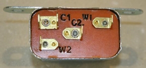 Internal workings of a 6RA relay If we now turn to the internal workings you can clearly see the Coil (or winding) in the centre of the photo. The coils are wound on an insulating former (the Bobbin) which is fitted over a soft iron Pole piece, the circular part protruding from the top of the Bobbin. Note too, the thick silver coloured iron frame that is fixed under the Coil and supports the Armature that is suspended above the Pole piece. The phosphor bronze spring that carries the armature, called the Blade, can be seen riveted to the frame and extends to the right to carry the Contact, the button shaped piece top right, directly under it is the other Contact which is connected to Terminal C1 via the silver coloured metal strip. The Pole piece is riveted through the base and is actually the connection for the Contact to Terminal C2. When current is passed through the Coil via Terminals W1 and W2, a magnetic flux is set up in the Pole piece which flows through the air gap that you see just above the Pole piece and under the Armature, back to the Frame and thus back to the Pole. This flux causes a magnetic force that attracts the Armature, closing the air gap and moving the upper Contact downwards toward the other Contact, thus making the electrical circuit. Soft Iron is the material of choice as it has little remanence, or lack of residual magnetism, which means the magnetic field collapses quickly when the current through the Coil stops and the Armature is no longer attracted.  Now the circuit is made, current will flow from Terminal C2 via the frame, the riveted spring Blade to the upper and then the lower Contact and out via Terminal C1 which is riveted to the metal strip that supports the lower Contact. This metal strip has another function that isn't immediately obvious, during final test after assembly the strip, which you will notice has a kink, is tweaked by the test operator to position the lower contact immediately below the upper. This is clear in the following photo. The Contacts might seem to the layman to be simply a couple of buttons made of a material that conducts electricity well, but most of the development effort in relays in the last 100 years has been in this area. The choice of metal used depends on the duty the | 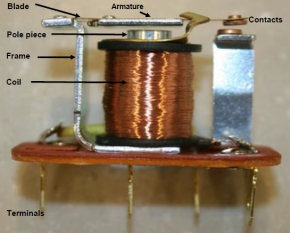 relay is required to perform, there are myriad choices and the manufacturer will have taken into account the operating environment, vibrations, life time cycles and many other factors such as pressure and speed of operation. The Contacts are arranged so that they do not appear to align very well, but this is deliberate, because as they come together the springy Blade bends a little and the Contacts move axially allowing them to "wipe" against each other, giving a slight cleaning action. Too much wipe introduces wear, so this has to be carefully controlled. The spring also exerts a force on the Contacts that keeps them together. A certain pressure is necessary to ensure low contact resistance. 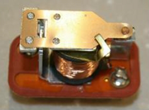 The top view of the 6RA relay workings reveals a curious piece of bent brass that protrudes over the top of the Armature. Despite its crude construction, this is a very critical part of the relay and should not be bent or moved at all. Its function is to limit the size of the air gap between the Armature and Pole piece so that when the Coil is energized the Armature is instantly attracted. If the gap is too large the Armature may not pull in, too small and the contact separation may be too little. Contact separation is also important when switching an inductive load, such as a motor or a solenoid, there is a voltage generated in the windings of a motor that is in opposition to the normal and depending on the magnetic properties of the iron and the assembly may be many times higher than the humble 12 volts being switched. Too little separation can allow this voltage (or back emf as it is known) to cause arcing that pits the contacts and erodes them. In more serious cases it could actually cause arcing which may weld them together. An important consideration too is the vibration that the relay will experience in its daily life. If the relay is subject to shock loads caused for example by pot holes in the road it isn't difficult to understand that the force on the Armature may be sufficient to cause the Contacts to momentarily separate. Usually the manufacturer will have determined the correct orientation for the relay mounting. With a 6RA, bolting it to the bulkhead is probably the best possible location, although under a heavy bump and rebound there may be a slight axial displacement of the Contacts and momentarily loss of electrical contact. Substituting a modern relay Because of the vibration with a car, it probably isn't a good idea to use substitute relays that are not designed for automotive use. They may work well in a stationary switchboard and handle huge currents, particularly AC, very well, but they will be unreliable when trying to switch the DC load of say, two cooling fans on a V8. They will also not be rated for the type and frequencies of vibration and temperature range experienced in automotive use. The resistance between any two Contacts is usually measured in milliohms (thousandths of an ohm) which is not actually very easy to do without laboratory equipment, but a little thought and some simple arithmetic will show the effect of an increase in contact resistance. If the Contact was originally 10 milliohms (0.01 Ohms) the heat generated when a current of 20 amps was flowing would be 0.01 Ohms x 20 Amperes = 0.2 Watts. This amount of heat is pretty easy to dissipate to the air around the contacts and is of little or no concern. Now imagine that the | 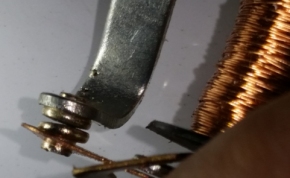 spring blade is getting old, the contact force is reduced and the contacts are misaligned and making contact only on a small contact area. The contact resistance may have increased to 100 milliohms (0.1 Ohm) then the calculation is very different; 0.1 Ohms x 20 amperes = 2 Watts. This amount of heat isn't so easy to dissipate and will cause deterioration in the contact force and increase the resistance, leading to an early failure. Corrosion is a source of 6RA failure The 6RA relay is prone to another curious failure mode; the construction of the relay is riveted and depending on the skill of the operator and the setup of the press to do it, there may be a small resistance between the various parts, particularly at the rivets to the Faston or Lucar blades. Over time the penetration of moisture can result in corrosion setting in - the environment in the engine bay is a very nasty place, so there must be airflow, but when it's raining cats and dogs on the M1 a lot of water gets in there. What happens here is unexpected, the increase in resistance causes the blades and rivet to heat up and after some cycles the material of the rivet will lose its clamping force and resistance will increase, causing further heating. This becomes self-destroying as eventually the terminals will get quite hot, the heat is transferred to the Faston connector and this too will lose its temper and contribute, by lessened holding force, to further heating and leading to eventual burning of the Bakelite base and a failure just when you need the fans most. 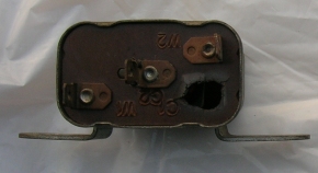 The best recommendation here is to replace the 6RA relay and at the same time replace the crimped on Faston connections on the wires if you have any doubt about their holding force. If they pull off and go back on easily they may have softened, so replacement is a must. Finally, when assembling the whole thing a quick spray of WD40 on the contacts blades makes them much easier to reconnect and will keep moisture away from the contact interfaces leading to long life. Fitting a modern relay in a 6RA case Steve Newton and I have been investigating if it is possible to shoehorn a modern cube relay into the 6RA case, but this appears to be impossible as the shape of the modern relay is just too large to fit inside the 6RA case snugly. For owners of cars for whom originality is paramount we suggest that the fans should be controlled by a modern relay mounted in a hidden location (or at least out of sight) and the original 6RA relay left on the bulkhead with wiring intact, but disconnected. We will continue to investigate this modern relay upgrade idea and if and when more compact relays become available details of the conversion will be released. Testing a 6RA relay While searching in my garage for a cube relay to investigate the possibility of fitting it inside the 6RA case, I came across a small device that I bought from Maplin a year or so ago that may be interesting. It is called the Automotive Relay Tester and good value at only £9.99. The test it performs is quite simple, it switches a small load across the contacts ten times in succession and measures the contact resistance every time. Repeatability, i.e. if the tester reads a similar resistance on each of the 10 cycles, it will give an indication that the relay is healthy, if there are any failures [i.e. one or more cycles result in higher contact resistance] then it assumes the relay is faulty. This is a quick and easy way to decide if the relay is at fault or not, unfortunately it doesn't test under high load, but I am considering if it might be possible to modify it with some extension wires to test a 6RA relay. Full article |
| V8
information and support See our popular V8NOTES listing, information gateways, top tips, spares and services specialists and spares for sale and wanted. | V8
Workshop Notes Information Gateways Top tips for new V8 enthusiasts | Technical
topics Spares & services specialists V8 spares for sale and wanted |