380
Fitting
dual petrol pumps to a V8
Gordon Hesketh-Jones (Harvest Gold 1904)
from Cornwall uses his V8 for touring in Europe so reliability is a key concern
for him and one area is the reliability of his SU fuel pumps. Here Gordon explains
how he has added an additional fuel pump as a standby should the other one fail.
(Jun 08)
I
have suffered four failures of the SU-Burlen petrol pump over a five year period
- two of these failures whilst touring abroad when replacement on the side of
the road is both inconvenient and difficult. So finally decided to do the obvious
thing - to plumb my spare pump into the fuel system rather than have it passively
lying idle in my on-board spares kit. The additional pump is wired in so that
it can be switched in should the principal pump fail.
To be fair to
SU-Burlen, I have read in various online chatrooms how modern fuels are attacking
rubber seals and/or aluminium, and we have to remember that BMW had to cope with
many of engine failures some ten or twelve years ago when their aluminium parts
were damaged by the high sulphur content in UK petrol. So, I am not too critical
of SU-Burlen and they did send me two new pumps free of charge.
Probably
the first task is to decide where the second fuel pump is to be located, and to
look at how the extra pipes will run. In my case, many years ago I replaced my
twin 6 volt batteries with a single 12 volt battery located in the nearside battery
box so I was then able to line the offside former battery box with ¾"
marine plywood so that I could use it for carrying my spares. The rear-facing
back of this box was an easy choice for me, but other alternatives would be in
the unused part of the battery frame, or projecting inside the boot by making
up a bracket as used on the rubber bumper MGBs and V8s. The materials to be used
would be approximately 30" of fabric reinforced 12mm rubber pipe, some 12mm
tee pieces and approximately 18" of the thin clear plastic pipe (and a Tee
piece) as used on windscreen washers. All of these should be available at your
local MG dealer or major motor accessories chains such as Brown Bros and Halfords.
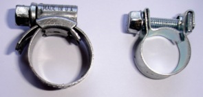
The most important parts are the correct type of hose clips. Normal
Jubilee clips will not work because
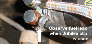
Leak
from a Jubilee clip.
(Photos: Gordon Hesketh-Jones)
|
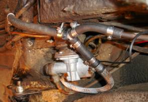 The plumbing for the dual fuel
pump installation. when
you
use the small diameter versions they assume an oval shape when tightened and petrol
will seep out no matter how tight they are made - the photos show a leak from
a Jubilee clip. The other photos shows the unfortunate deformation of a Jubilee
clip quite clearly. The correct clips for fuel lines have the bolt and captive
nut at the side and do stay correctly
circular. I bought the correct mild steel clips from our local MG dealer for 50p
each and some spare stainless steel versions at Silverstone for 80p each.
The plumbing for the dual fuel
pump installation. when
you
use the small diameter versions they assume an oval shape when tightened and petrol
will seep out no matter how tight they are made - the photos show a leak from
a Jubilee clip. The other photos shows the unfortunate deformation of a Jubilee
clip quite clearly. The correct clips for fuel lines have the bolt and captive
nut at the side and do stay correctly
circular. I bought the correct mild steel clips from our local MG dealer for 50p
each and some spare stainless steel versions at Silverstone for 80p each.
The next decision relates to just where you will locate the switch to change
over from one pump to the other. If you are feeling pessimistic then the switch
needs to be on or under the dashboard for easy and quick access, but if (like
me) you feel that by simply installing the second pump the immutable law of S.O.D.
will apply and you will never have another failure, then the switch can be in
the boot. The switch itself needs of course to be a changeover switch, with three
terminals ON-OFF-ON. None of the standard switches on MGs conform to this pattern
but Demon Tweeks list the LMA plastic version at £4.18 or the much better
sealed version from Trillogy at £21.50. Locating the switch in the nearside
channel of the boot means that you can easily use the existing 1 ½"
diameter hole in the side of the boot for the cable run. You can even opt not
to drill a hole for mounting the switch so as to avoid knocking or damaging it
with luggage or tools, and bury it instead under the carpet, obviously insulating
the terminal first.
Once you have thought through the job properly, it
is simply a matter of spending a few hours on your back under the car, remembering
to use good quality pipe and hose clips, and making sure that the rubber pipe
runs are not too long so that they can create sharp bends and petrol flow restriction
as they settle in. Remember too the standard trick when working on the MGB fuel
lines - slacken off the nut holding the pipe into the tank union by approximately
three quarters of a turn. This will allow some air in the pipe to create an air
lock. Certainly some petrol will come out of the rest of the pipe when you undo
it at the original pump, but it will be less than a cupful. Cable ties were used
to make sure that the rubber pipes stay in place properly. |