|
340
Review of the B&G Castor Reduction
Kit
An improved castor
angle reduction kit has been produced for chrome and rubber bumpered
MGBGTV8 and MGB models by Brown & Gammons, the MG specialists
at Baldock. This note from Chris Hunt Cooke and Victor Smith describes
how fitting the kit rotates the crossmember forwards thereby reducing
the castor angle, reviews the engineering improvements, provides
some useful background information on the need for positive castor
to self-centre the steering at speed and give good steering response,
and describes how reduced castor with modern radial tyres gives
a reduced steering load. (Jan 06)
Heavy steering
has been a noticeable feature of the MGB and the MGBGTV8 models
It is caused by the 7 degrees of positive castor needed to produce
the self centring steering action with the cross ply tyres available
in 1962 when the model was first produced. Since that era radial
tyres have been developed along with improved rubber compounds with
greater grip which have the effect of increasing the steering load,
particularly with tight cornering or cornering at speed. As modern
tyres are far more directional, less self-centring force is necessary
and so less castor is required. Consequently these tyre changes
provide scope for reducing the castor angle and thereby obtaining
the welcome benefit of lighter steering.
The B&G
Castor Reduction Kit is designed to do two things - first to
reduce the castor angle by 3 degrees from the original 7 to 4 degrees
and second to maintain the integrity of the mounting of the crossmember
to the chassis leg. It is worthwhile understanding how this new
kit achieves that with well thought through engineering details
which ensure the mounting studs (or bolts) continue to be positively
located in taper seats in the chassis legs and the rubber mounting
pads are not crushed to achieve an accurate castor angle setting.
This is seen as an improvement on another kit currently available,
which when fitted results in the taper of the stud being held away
from its seating and the rubber pad being crushed when the assembly
is torqued up.
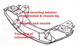
How is the
crossmember mounted to the chassis leg before the castor modification?
The MGB front cross member is fabricated out of pressed and welded
steel sheet and is mounted on the underside of the chassis legs
(which are box sections extending forwards from the monocoque) with
four high tensile steel mounting studs which are positively located
on taper seats into the chassis leg. In the attached drawing of
the crossmember you can see on either side that the topmost part
is the platform with four holes on which the lever arm shock absorbers
are mounted. Just inboard from those platforms are the two large
holes on either side through which the crossmember is bolted to
the chassis legs by the mounting studs.
Front crossmember is fabricated out of pressed and welded
steel sheet and is mounted on the underside of the chassis legs
(which are box sections extending forwards from the monocoque) with
four high tensile steel mounting studs (or bolts) which are positively
located on taper seats into the chassis leg. (Drawings: Parts Manual
and B&G)
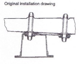
Those mounting studs have screw threads at the top and bottom
and a thicker plain section in the middle, with a taper at the top.
The intention of the design is that the taper locates to a corresponding
taper seating in the bottom of the chassis leg. Hence the mounting
bolt is positively located in the centre of the hole in the chassis
leg when it is bolted up with a torque of 56 lbft.
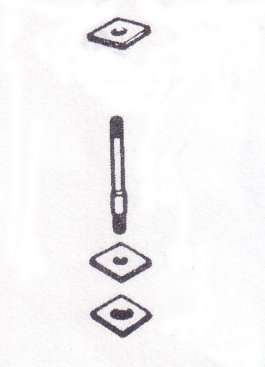
Mounting stud (or bolt) with upper pad, lower pad and
steel plate with the locking nut under. Note the mounting bolts
have screw threads at the top and bottom and a thicker plain section
in the middle, with a taper at the top. (Diagram: V8 Parts Manual)
This leaves the bottom part of the mounting stud protruding below
the chassis leg with a plain section, and beneath that a narrower
threaded section forming a shoulder at the end of the plain section.
Over the plain section of the stud is fitted a rubber pad which
acts as a packing piece between the chassis leg and the mount on
top of the fabricated crossmember. This is held up by a rectangular
washer with a smaller diameter hole so that the washer sits on the
shoulder of the plain section of the mounting stud but is held in
place by the bottom locking nut. The pressure on the rubber pad
between the chassis leg and the crossmember is therefore limited
so crushing is avoided.
|
What
is castor?

The castor angle is the angle, measured in degrees,
formed between the axis of the kingpin and the perpendicular
to the ground looking at the vehicle from the side. As the angle
is formed longitudinally relative to the vehicle, it is more
exact definition is longitudinal castor angle. In practical
terms it is known more simply as castor angle. The castor angle
given to the kingpin creates two important phenomena for the
ride and handling of the vehicle - first stability in terms
of maintaining the straight line of travel of the vehicle and
the extent to which the steering self centres after turning
and second the tilt of the wheel which occurs during turning.
The
stability phenomenon is created on the basis of the distance
between the point at which the kingpin axis extension falls
(in relation to the direction of travel) and the point of contact
between the tyre and the ground. In the case of positive caster
angle (where the kingpin extension falls ahead of the point
of contact between the tyres and the ground), the wheel is pulled,
as it is the line of application of the force applied to the
axis that passes in front of wheels mid point without taking
the direction of travel into account, and each attempt made
by the wheel to deviate from straight line travel will be counteracted
by the straightening couple generated by the force and by the
rolling resistance of the wheel. With negative castor the wheel
is pushed as it is the line of application of the force applied
to the axis passes behind the mid point of the wheel. Consequently
the best stability condition for straight line travel is obtained
with a positive castor angle. In this case the phenomenon of
"wheel wobble" and the consequent effects on steering
are avoided. The different behaviour of the wheels can be verified
practically by driving the same vehicle in forward gear and
then in reverse. |
|
How
does the kit reduce the castor angle?
The method used to reduce the castor angle is to rotate the crossmember
towards the front of the vehicle by providing a precisely engineered
stainless steel packing piece between the front crossmember fixing
points and the underside of the chassis leg. Since the steel packing
has used some of the length of the plain portion of the mounting stud,
a steel collar is supplied with the kit which has to be fitted. In
effect it extends the plain portion of the mounting bolt back to its
original length. Without this collar the rubber mounting pads would
be compressed too much thereby ruining the mounts and the ride quality
- and of course the crushing would give rise to variances in the castor
angle, even between each side of the vehicle. New slightly shallower
high tensile steel locking nuts are provided in the kit to fit the
reduction in useable thread length of the mounting studs.
Steering
rack packing pieces
Because the angle of the crossmember upon which the steering rack
is mounted will have changed slightly in relation to the chassis legs,
the body of the steering rack mast will quite probably no longer align
with the steering universal joint. The steering rack mounts will therefore
have to be packed at the front in order to realign the rack with the
universal joint. Six packing shims are included in the kit.
Can a V8 enthusiast fit the kit?
The B&G Castor Reduction Kit can be fitted by a competent DIY
mechanic but as with most matters relating to vehicles, the modification
does need to be carried out with the right equipment and conditions
and sufficient knowledge, mechanical skill and aptitude. If you have
any doubts whatsoever, the kit should be fitted by a professional
mechanic. B&G estimate that fitting the castor reduction kit requires
approximately three hours work.
Now a few cautionary notes regarding RV8s and Heritage shells and
crossmembers
There is a mistaken belief about that the castor angle on the RV8
is the same as the MGB and V8 and so the castor reduction kit can
also be fitted to the RV8. This is incorrect as the castor
angle on the RV8 is 3 degrees 48 min +/- 54 mins (see the RV8 Repair
Manual AKM7153ENG) so using a castor reduction kit that would remove
3 degrees of castor would leave only 0 degrees 48 mins +/- 54 mins
which is not sufficient. In addition the crossmembers supplied by
the British Motor Heritage plant at Witney, whether supplied individually
or incorporated in new BMH shells, already have a reduced castor angle.
BMH have confirmed that the castor angle reduction was incorporated
on the crossmembers they supply. Therefore any MGB or MGBGTV8 fitted
with a Heritage crossmember, or even in some rare cases fitted with
an RV8 crossmember, should NOT be fitted with a castor reduction
kit.
Prudent check for cracked steering rack mounts While you are
working in this area on fitting the castor reduction kit, it is well
worth checking the condition of the steering rack mounts for any hairline
cracks or more serious fractures. These have been reported in detail
together with the information on the new strengthening gusset supplied
by B&G. See V8NOTE338. A routine check
on the condition of the mounts should be included in your annual servicing
checklist.
The B&G Castor Reduction Kit (AHH6195 CASTOR) is available
now from stock at £29.95 including VAT. The kit includes comprehensive
fitting instructions and detailed diagrams. The Steering Rack Mount
Strengthening Gusset (AHH6195 BRACKET) is also available from
B&G. They can carry out the inspection for you and if cracks are
discovered, supply the gusset and MIG weld it to the mount and crossmember
at their Baldock workshops. For details of the new strengthening gusset
see V8NOTE339. |