

| 333 Fitting a TE Low Brake Fluid Sensor The sensor developed by Bob Owen (Blaze 1675) at TE Electronics in Berkshire is a useful device to warn you of low fluid levels. Here Victor smith (Harvest Gold 1089) describes fitting an LBFS in easy stages. (Jul 05) 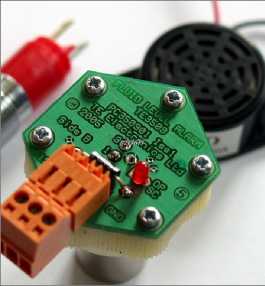 The installation described here is for a TE Low Brake Fluid Sensor (or LBFS) fitted to a chrome bumper MGBGTV8 which is of course negative earth. The battery should be isolated as a precaution before starting the installation by removing the positive battery terminal clamp. The stages are set out in some detail to assist V8 enthusiasts who are not too familiar with autoelectrics. Establish which terminal on the under bonnet fuse box is both fused and ignition switched On the V8 this is usually terminal 6 which has green wires connected to it - see the extract from the circuit diagram below where terminal 6 is the second up from the bottom on the RHS. 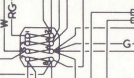 In the diagram of the fuse box from page 39 of the MGBGTV8 Driver's Handbook AKMD 8423, the fuse between terminals 5 and 6 is marked with a 4. Terminal 6 is on the RHS of that fuse. Examine the wiring kit Lay it out so you can see the bleeper, LED, orange LBFS plug and the wiring with two Faston connectors. The bleeper and LED go inside the cockpit and the orange LBFS plug and Faston connectors go in the engine bay, so the first thing to do is to split the two parts. Then the small cables from the bleeper and LED can be pushed through the wiring grommet in the bulkhead from the cockpit to a point alongside the brake fluid reservoir in the engine bay. Do not attempt to push the orange LBFS plug still attached to the wiring through the grommet as it is too large and after 30 years and more, the grommet will be soft and will simply pop out of the hole in the bulkhead - you will then have to struggle to get the grommet back into place.  Disconnect the wiring for the bleeper and LED from the orange coloured LBFS plug For this you will need a small (2.4 to 2.5mm) flat bladed screwdriver to get at the small screws holding the cable clamping plates in the plug. You can see the recessed screw holes in that plug in the photo at the head of these notes. These screwdrivers are sometimes called "jeweller's" screwdrivers. The two cables you need to disconnect from the plug are the small "orange" and the small "black" cables both leading to the LED and bleeper - see the LBFS wiring diagram. 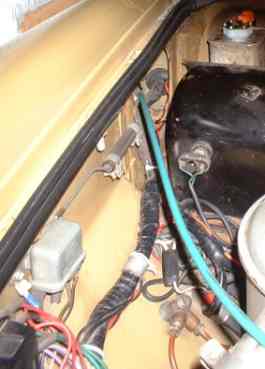 Circular rubber grommet is tucked away alongside the black brake master cylinder cover box. Locate the grommet You will find it by placing your head on the driver's seat squab and looking to the right and slightly above where the driver's right leg would be when sitting in the car. From the engine bay, you can see the other side of this grommet by looking down the side of the black brake master cylinder cover box into the narrow gap with offside wing. Routing the cables Attach the two small cables to a knitting needle with some insulating tape and then very gently push the needle through a small gap in the grommet alongside the point where the main wiring harness passes through the grommet. Then move round to the engine bay and with a pair of long nose pliers, reach into the narrow gap and carefully pull the head of the needle up so you can remove the two small cables and pull them through. Remove the knitting needle and return it to your wife or partner's workbox before she notices! 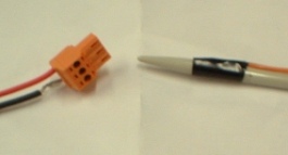
Knitting needle used to ease the small cables through the rubber grommet with the orange LBFS plug with the cables removed. Carefully wind the wire strands of each small cable and insert them in the orange LBFS plug First the orange cable in the centre position. Make sure the clamping screws are sufficiently undone to allow the cable to go fully home in the small cable clamp and then tighten down the screw firmly. Next wind the small black cable with the black negative cable with the earthing Faston on the other end to create a neat combined cable end, and push it fully home in the small cable clamp and tighten up firmly. Wind on the black plastic spiral sleeve over the four small cables from the orange LBFS plug back along the length of the sleeve By arranging the cables so they are neatly packed together over the length of the sleeve, it makes a very neat cover for those cables. Gently pull any excess cable (orange and black cables to the bleeper and LED) through to the cockpit. 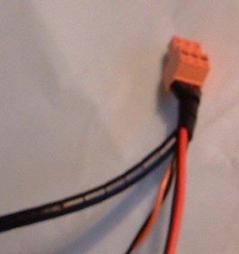
Winding the plastic sleeve on four small cables to make a neat installation. |
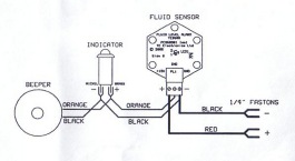 Wiring diagram for the TE LBFS kit - a full size diagram is provided with the installation instructions Tidy the cables under the dashboard Run those small orange and black cables along the narrow horizontal rail under the righthand side of the dashboard and fix with two ty-raps - one at each end. Cut off any surplus length of ty-rap to around a centimetre of the ty-rap non slip fixing point. Fix the bleeper on the flat vertical panel just to the right of the steering column using the double sided tape If you prefer the bleeper can be fixed with two No 4 ST screws which will of course involve drilling the metal surface. Next fix the LED Here you have a choice - first the easiest is to attach the LED to a convenient section of wiring adjacent to the steering column so the LED can be seen just above your knees when in the driving position, second you can fix a small bracket to the upper righthand side edge of the radio console and mount the LED in it, or you can drill the crackle finish dashboard on the extreme righthand side (see photo) and mount it flush in the surface. 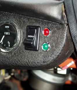 LED mounted in the crackle finish dashboard alongside a cooling fan override switch and green LED. The alarm signal is a rapid flashing of the red LED which can be mounted in the dashboard or other convenient location plus synchronised bleeping. You will see Bob has also installed a cooling fan override switch and green LED. (Photo: Bob Owen) Route the black and red cables in the engine bay These run from next to the black master cylinder cover box down and alongside the main wiring harness to a point just under the fuse box but before the line fuse. Tuck the LBFS cables under the main harness and fix at three points along that cable route with the ty-raps to leave the wiring looking neat and concealed under the main harness. Fix the negative Faston Unscrew the lefthand screw fixing the fan relay to the inner wing and attach the earthing Faston tab for a spade connector, then run the black earth cable up and attach the negative Faston connector at the end of that cable to the earth tab. 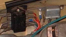
Here you can see the positive lead with the blue shrink wrap fixed to the "piggy back" Faston on fuse box terminal 6 and the negative lead attached to the Faston under the left hand screw of the relay Terminal 6 at the fuse box Pull off the spade connector from terminal 6 of the fuse box - note green cables are attached to that spade connector. You can check this on the extract of the MGBGTV8 wiring diagram below. Run up the red cable with the piggy back Faston connector at the end, and attach to terminal 6. Replace the spade connector to the tab on the piggy back Faston. Thoroughly check your installation before reconnecting the battery terminal clamp and testing. Attach the orange plug to the LBFS unit and position next to the brake fluid reservoir Do make sure that when you insert the plug into the top of the LBFS unit mounted on a plastic reservoir cap, that the screw holes of the orange plug are uppermost. At this stage you have not removed the existing plastic cap from the reservoir and have not put the metal body of the LBFS into the brake fluid. 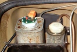
Turn on the ignition key whereupon the bleeper will sound once and simultaneously the LED will flash once. This is the reassuring sign or "LBFS Armed Signal" that your LBFS unit and alarm are operating correctly. Test your TE LBFS With ignition still on, after around half a minute the low brake fluid alarm should sound - a series of simultaneous bleeps and LED flashes. Of course this is a correct alarm as the unit under test is positioned outside the reservoir and is not immersed in brake fluid - so the level is very low, in fact non existent! Put the sensor in the reservoir Turn off the ignition and remove the plug from the LBFS. Remove the existing plastic reservoir cap and check the brake fluid level is at the correct level. Screw on the LBFS mounted on its plastic cap in place of the existing cap Then connect up the orange plug to the socket on the top of the LBFS. Do make sure the plug is up the right way - the screw holes for the cable clamps on the orange plug should be uppermost. Test again with the unit installed Turn on the ignition again whereupon the bleeper will sound once and simultaneously the red LED will flash once giving you a reassuring confirmation the unit is working correctly. If the fluid is at the correct level, no alarm should sound after a minute of so. Put the existing cap in a safe place Wrap the existing plastic cap in a piece of kitchen paper and pop the bundle into one of the sealable plastic bags provided with the kit and place it in the glove box. Fault checking TE Electronics Ltd Tel: 0118 933 2533 & Fax: 0118 933 1224 sales((atat))teelectronics.co.uk (note we use this email address format to block spammers automated email address harvesters, just use @ as usual) www.teelectronics.co.uk |