17
Heavy
breathing on the V8
Peter Laidler (Harvest Gold 0811) from Oxfordshire provides
an interesting article which explains how the V8 inlet manifold
works and which carburettor feeds which cylinders.
(Jan 80) Uploaded:
250212
The
carburettors used on the MGBGTV8 are SU HIF6 units and although
they are not foolproof by any means, they are possibly the best
choice of the easily available carburettors for this engine.
Unlike the old HS type, the HIF6 type are integral and the spindles
have airtight seals, and leaks are probably non-existent. However
having said that, by now most MGBGTV8s are getting old and I
suggest that as soon as the carburettors are removed from the
engine for any reason, take the opportunity to refurbish them
with two sets of seals available under part number GSU500. The
inlet manifold BHH1017 sat on top of the adaptor carburettor
BHH988, then the two trusty HIF6 SUs.
It is generally accepted that where there are two carburettors
per engine as on the MGB then the front carburettor feeds the
front two cylinders and the rear carburettor feeds the rear
two cylinders. Likewise on the old Cooper S model, the left
hand carburettor feeds the two left hand cylinders and the right
hand carburettor feeds the right hand cylinders. Yes before
anyone tells me there is a balance pipe and one carburettor
can subsidise another, I accept this but what I have said is
basically correct. Now on this basis you would feel it would
correct to assume that with the mighty V8 that the left hand
carburettor feeds the left hand bank of cylinders and the right
hand carburettor feeds the right hand bank of cylinders. But
you would be wrong. Before I go any further I must clarify "left"
and "right" on the V8 - they are left and right as
viewed from the rear of the car. I am clarifying this now as
I have seen someone come drastically unstuck while viewing the
engine bay the other way round!
If anyone has seen the V8 inlet manifold you will have noticed
two big holes below where the adapter is bolted on. These holes
are called the plenum chambers. Two dictionaries give two definitions
of the word plenum - one states that it is a "place for
conditioned air" and the other states that it is "a
gathering chamber". They sum up the word plenum in its
V8 context - a gathering chamber for conditioned air, in this
case the 14:1 air petrol mix.
Let us now turn to these two chambers on the V8 unit, left and
right. At the outset I should stress that these are not connected
as the MGB unit and consequently one carburettor cannot subsidise
the other on the V8 unit. The left bank of cylinders are numbered
1, 3, 5 and 7 and the right bank 2, 4, 6 and 8. The left hand
carburettor has two feed tracts leading from the carburettor
directly to cylinders 1 and 7. Via number 1 cylinder tract there
is a takeoff to feed number 4 cylinder on the right bank and
via number 7 cylinder tract a takeoff to feed number 6 cylinder
on the right hand bank. That has dealt with the left hand carburettor.
The right hand is similar in that it has two feed tracts direct
to number 2 and 8 cylinders on the right hand side. Via the
number 2 cylinder tract is a takeoff to feed number 3 cylinder
on the left hand side. From number 8 cylinder feed tract there
is a takeoff to |
Back
to homepage
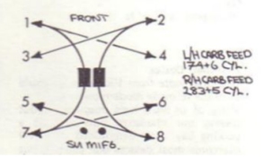
feed
number 5 cylinder on the left hand side.
I will briefly explain that I set up my
carburettors with a Colourtune, simply because I believe the
saying "the only way you can tell what is happening in
the cylinders, is to look inside" is true and that this
enables you to do just that. However this is only my personal
view. I say this as I refer to this item of equipment in the
next paragraph. I also use the Colourtune to set up the Webers
on our racing Midget.
You
can now see that for the purpose of setting up the air/fuel
ration of the left carburettor, it is essential to use the Colourtune
plug and observe the colour in the plug of cylinders number
1 or 7 as cylinders 4 and 6 are second best. Likewise to set
up the mixture of the right hand carburettor, use cylinders
number 2 or 8 and regard 3 and 5 as second best.
The
observant of you will now say "it doesn't look that the
V8 manifold is very efficient" and at first glance I would
have to agree, but if that were the case when you had set up
cylinders 1, 7 2, and 8 correctly, then cylinders 3, 5, 4 and
6 would be on the weak side. But strangely enough this is not
so - or as near as makes no difference and must show credit
to the designers who did their homework with this manifold set
up.
As
an afterthought, those of you who set up their mixture ration
by looking at the colour of the plug, then do not fall into
the trap of looking at the colour of the plugs in the drive
at home. That will simply show the condition of the plugs and
the air/fuel mixture "off load". Instead take the
car out for a thrash and at about 70 mph on a clear stretch
of road, switch off the ignition and coast to a stop and then
inspect the plugs which will record in terms of colour the condition
"on load" and adjust the carburettors accordingly.
Do not coast to a stop with the engine running out of gear as
this will the same as running "off load" on your drive.
SU booklets on the HIF carburettors
On the subject of carburettors, there are two publications available
from SU on the HIF4 and HIF6 carburettors. The part numbers
of the publications are:
BLMC
AKD7521 SU AUC9940
BLMC AKD7902 SU SUC9939A
Copies of both are available on the V8 website at:
SU publications
Tuning SU carburettors
There is also a useful book, Tuning SU Carburettors from Speedsport
ISBN 85113-0720-0 More |